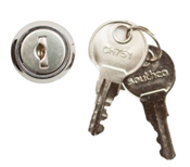
MFDC-xA Rack mount splice and termination optical cabinet
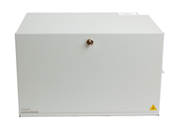
IP41 rating + Angled fit of adapters
MFDC-xA Connector Network Panel is the optical distribution frame that can be mounted on a 19” rack. It is designed for splicing pre-made pigtails, pre-terminated cables, and connectors that can be installed on site. The cabinet is made from a lightweight and solid aluminum-magnesium alloy, which makes it easy to handle during installation and operation and also helps keep transportation costs low.
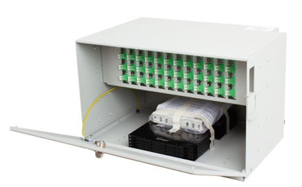
Incoming cables are connected to the side panel of the unit using a PG cable glands, which helps the MFDC-xA meet the IP41 rating. Inside of cabinet is a splice tray holder or bend radius protection to guide, store and organize excess slack of pigtails. This helps prevent damage to fibers before they are routed into couplings.
MFDC-xA cabinet is equipped with angled adapters which prevent direct eye contact with the fiber optic laser and reduce the risk of vision damage.
- Splicing and termination optical cable in one box
- Aluminum-magnesium alloy material providing low weight and low shipping costs
- Installation of adaptors under angle
- Splice cassette holder enables cable termination with the help of pigtail splicing
- Rating IP41
- PG16 cable gland and optionally grounding provisions
- Accepts the industry's most common connector types
- FTTH use - microtubes holder included
- Durable powder coat finish light grey color (RAL 7038), next color optionally on request
- Special front panel from luxury Stainless Steel Look (SSL) material meet IP41 rating
|
PART NUMBER |
RACK UNITS |
RATING IP41 |
DIMENSIONS (HxWxD) mm |
SHIP WGT (kg) |
|
MFDC - 2A |
2 |
– Special SSL front panel |
88 x 432 x 305 |
2.1 |
|
MFDC - 3A |
3 |
133 x 432 x 305 |
2.4 |
|
|
MFDC - 4A |
4 |
178 x 432 x 305 |
2.5 |
|
|
MFDC - 6A |
6 |
267 x 432 x 305 |
2.9 |
 |
 |
|
MFDC-6A-8-96-DLCF A-ZM/G front view |
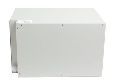
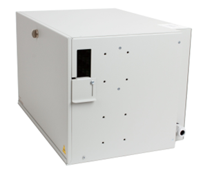
MFDC-6A-8-96-DLCF A-ZM/G back view |
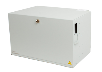 |
 |
|
MFDC-6A-8-96-DLCF A-ZM/G front right view |
MFDC-6A-8-96-DLCF A-ZM/G opened |
 |
 |
|
MFDC-6A-8-96-DLCF A-ZM/G side view (PG13.5) |
Grounding accessories - optional |
|
MFDC - xA |
|
- |
X |
- |
XXX |
- |
XX(F)1 |
|
-X |
- |
XX |
- |
/(G)2 - (UHV)3 |
|||||||||||||
|
|
|
|
|
|
|
|
|
|
|
|
|
|
|
|||||||||||||
|
x - Size (Rack unit) |
|
|
|
|
|
|
|
|
Front door option |
|||||||||||||||||
|
2 - 2U |
|
|
|
|
|
|
|
|
|
LM |
Metal door - Lock4 |
|||||||||||||||
|
3 - 3U |
A - Angled adapters |
|
|
|
|
|
|
|
|
ZM |
Metal door - Latch |
|||||||||||||||
|
4 - 4U |
+ IP41 rating |
|
|
|
|
|
|
|
|
LP |
Plastic door - Lock4 |
|||||||||||||||
|
6 - 6U |
|
|
|
|
|
|
|
|
|
ZP |
Plastic door - Latch |
|||||||||||||||
|
|
|
|
|
|
|
|
|
|
|
|
|
|||||||||||||||
|
|
|
|
|
|
|
|
|
|
Applications |
|
||||||||||||||||
|
X - Number of Splice trays |
|
|
|
|
|
|
M |
Multimode |
|
|||||||||||||||||
|
2 - 12 |
Number of splice trays KNS-12S |
|
|
|
|
|
S |
Singlemode |
|
|||||||||||||||||
|
|
|
|
|
|
|
|
A |
APC applications |
|
|||||||||||||||||
|
|
|
|
|
|
|
|
|
|
|
|||||||||||||||||
|
|
|
|
Fiber capacity |
|
|
Coupling type |
|
|||||||||||||||||||
|
Key lock(LM)4
|
Metal latch(ZM)
|
0 – 144 Fibers |
|
|
ST |
ST adapter |
|
|||||||||||||||||||
|
|
|
|
SC(F) |
SC adapter |
|
|||||||||||||||||||||
|
|
|
|
FC |
FC adapter |
|
|||||||||||||||||||||
|
|
|
|
E2(F) |
E2000 adapter |
|
|||||||||||||||||||||
|
|
|
DSC(F) |
SC duplex adapter |
|
||||||||||||||||||||||
|
|
|
DLC(F) |
LC duplex adapter |
|
||||||||||||||||||||||
|
|
|
DE2(F) |
Duplex E2000 |
|
||||||||||||||||||||||
Note: 1) F –Fixed adaptors by screws
2) G – Grounding option – protection grounding wires installed, see datasheet CMS_01-02_EN-accessories
3) UHV – Vertical unit holder
4) Optional –The same key for multiple ordered cabinets

