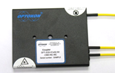
SFT 01x02 Singlemode Couplers

SFT-SWB Wavelength Independent
SFT-S35 Dual Windows Wideband
OPTOKON SFT-SWB wavelength independent couplers/splitters are designed to transmit optical signals within the full CWDM wavelength spectrum. With its innovative Fused Technology Process, the SFT series couplers have proven to provide exceptional characteristics for all applications demanding critical performance. These ultra reliable devices feature low backreflection, low insertion loss, and high port isolation over wide temperature and wavelength ranges. The SFT couplers are designed to divide and/or combine different optical signals in optical fiber systems. Splitting ratios can be customer specified between 1%:99% and 50%:50%. Various types of pigtailing and connector terminations are available to meet your requirements. Available in a wide variety of packaging configurations The OPTOKON SFT-S35 dual windows wideband series are operable in both 1310 nm and 1550 nm wavelength range.
- Low insertion loss
- High port isolation
- Custom defined specifications
- Environmentally stable
- Wavelength independent - full CWDM spectrum
|
ITEM |
Dual Window Wideband Couplers |
|
Operating Wavelength, nm |
S35: 1310 ± 40 and 1550 ± 80 SWB: 1250 – 1650 (CWDM wavelength range) |
|
Typical Excess Loss, dB |
0.2 |
|
Uniformity, dB (50:50) |
≤ 0.8 |
|
Thermal Stability, dB (peak-peak) |
< 0.2 |
|
PDL, dB (50:50 coupling ratio) |
< 0.15 |
|
Port Configuration |
1 x 2 or 2 x 2 |
|
Coupling Ratio |
1:99 to 50:50, (50:50 standard) |
|
Insertion Loss1), dB |
Refer to the coupling ratio vs. Insertion loss chart |
|
Directivity, dB |
> 50 |
|
Return Loss, dB |
> 50 |
|
Operating Temperature2), °C |
-40 to +85 |
|
Storage Temperature2), °C |
-50 to +85 |
|
WARNING |
This product should never be installed in an optical network handling above Class I emissions |
Note: 1) Without connectors
2) Conditioned by the cable type
Block diagram:

|
Coupling Ratio vs. Insertion Loss: |
Coupling Ratio PDL Conversation Chart: |
||
|
Coupling Ratio (%) |
Insertion Loss (dB) |
Coupling Ratio (%) |
PDL (dB) |
|
50 / 50 |
3.6 |
> 40 % |
0.15 |
|
40 / 60 |
4.8 / 2.7 |
30 to 39 % |
0.20 |
|
33 / 67 |
5.7 / 2.2 |
10 to 29 % |
0.30 |
|
30 / 70 |
6.2 / 1.9 |
1 to 9 % |
0.35 |
|
20 / 80 |
8.3 / 1.3 |
|
|
|
10 / 90 |
11.7 / 0.7 |
|
|
|
5 / 95 |
15.2 / 0.4 |
|
|
|
1 / 99 |
23.3 / 0.2 |
|
|
Packaging variants:
 |
|
|
|
|
SFT-SWB-01x02-50-BFS-NC-NC |
SFT-S35-01x02-50-LTS-NC-NC |
SFT-S35-01x02-50-CM1-NC-NC |
|
|
|
|
|
|
|
SFT-S35-01x02-50-CM3-NC-NC |
2x SFT-S35-01x02-50-RM-NE2-NE2 |
SFT-S35-01X02-WM-NE2-NE2 |
- Telecommunications
- Local area network
- FTTH - PON
- CATV
- Testing instruments
|
SFT |
- |
XXX |
- |
01 x 02 |
- |
XX |
- |
XXX |
- |
NC-NC |
|
|
|
|
|||||||
|
|
|
|
|
|
|
|
|
|
|
|
|
|
|
|
|
||||||
|
|
|
|
|
|
|
|
|
|
|
|
|
|
|
|
|
||||||
|
grade |
wavelength |
|
# port |
|
|
|
no input and output connectors3) |
||||||||||||||
|
S35 |
1310/1550 nm |
|
01 x 02 |
|
|
|
connector type - according to CON_14-01 |
||||||||||||||
|
SWB1) |
1250 - 1650 nm |
|
02 x 02 |
|
|
|
|
(Jumper Ordering Code) |
|||||||||||||
|
|
|
|
|
|
|
|
|
|
|
||||||||||||
|
|
coupling ratio |
|
basic packaging |
||||||||||||||||||
|
|
50 |
50/50 |
|
BFS |
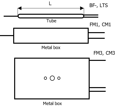
bare fiber 250 µm, tube L=54, Ø=3 mm |
||||||||||||||||
|
|
40 |
40/60 |
|
LTS |
Fiber 0.9 mm, tube L=54, Ø=3 mm |
||||||||||||||||
|
|
30 |
30/70 |
|
FM1 |
fiber type, metal box 100x15x9 mm |
||||||||||||||||
|
|
20 |
20/80 |
|
CM1 |
cable type, metal box 100x15x9 mm |
||||||||||||||||
|
|
10 |
10/90 |
|
FM3 |
fiber type, metal box 100x80x10, stackable |
||||||||||||||||
|
|
05 |
5/95 |
|
CM3 |
cable type, metal box 100x80x10, stackable |
||||||||||||||||
|
|
01 |
1/99 |
|
|
|
||||||||||||||||
|
|
other2) |
|
additional packaging |
||||||||||||||||||
|
|
|
CAPM |
OPTOKON cassette |
||||||||||||||||||
|
|
|
SC |
splice cassette |
||||||||||||||||||
|
|
RM |
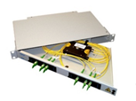
rack mounted unit (MCNP-1U) |
|||||||||||||||||||
|
|
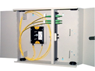
WM |
wall mounted box (MPIC-4) |
|||||||||||||||||||
Note:
1) ±0.3 dB tolerance
(1370, 1390, 1410 nm IL increased for 0.2-0.3 dB)
2) please define
3) standard fiber/cable length = 1 m


